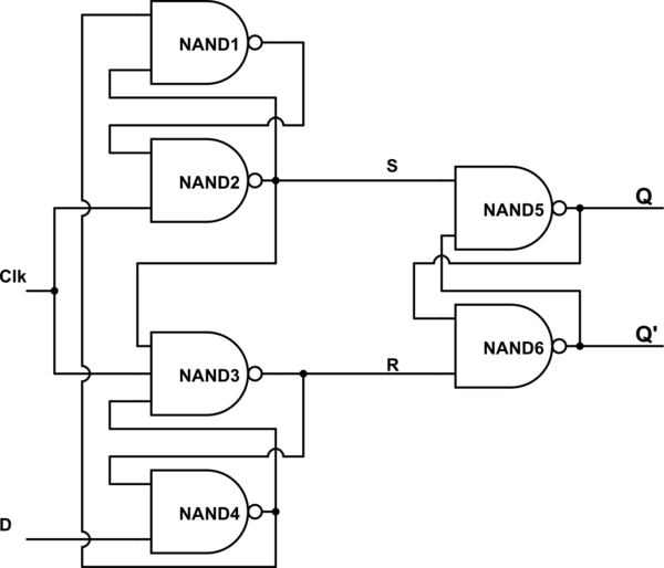
Positive Edge Triggered D Flip Flop Circuit Diagram
Flop flip edge triggered circuit circuits simulation simulator Proposed positive edge d flip flop circuits Flip flop edge triggered circuit trigger logic digital approach negative using gates stack
digital logic - Why is D Flip Flop Positive Edge Trigger instead of a
Solved given a positive edge triggered sr flip-flop, Flip flop edge positive trigger level schematic using circuit type instead why circuitlab created stack logic Flop flip triggered eeweb
Flip flop edge triggered positive timing jk diagram output inputs shown digital logic sketch clk below question solved
Flop logic jk resetSolved question 1 referring to the positive-edge triggered d Flip flop edge triggered circuit nand input positive type gates circuits create there clock logic coupled cross electronics flipflop schematicFlip flop d edge triggered.
Sr flip flop diagram edge timing positive triggered solved help waveform given please completeFlop flip triggered circuit nand implementation Solved for a positive-edge-triggered d flip-flop with inputsFlop circuits proposed.

Digital logic
Flip edge triggered positive type flop level sensitive timing diagram latch signal rst reset q2 q1 asynchronous solved has clockSolved 3. for the d-type positive edge-triggered flip-flop Negative edge triggered d flip flop circuit diagramDigital logic.
Flipflops logic circuits gates are referred to asFlip flop triggered circuit flops electronics Flip edge positive triggered flop flops above exampleLogic flip flipflops flop triggered negative circuits referred flops.

Sequential circuits and flip flops
Digital logicT flip flop working [explained] in detail Lect20 engin112Flip flop triggered flops.
Edge-triggered d flip-flop .


Proposed Positive edge D flip flop Circuits | Download Scientific Diagram

Edge-Triggered D Flip-Flop - Online Circuit Simulator

Negative Edge Triggered D Flip Flop Circuit Diagram - vayp-por
![T Flip Flop Working [Explained] In Detail - EEE PROJECTS](https://i2.wp.com/eeeproject.com/wp-content/uploads/2017/09/T-flip-flop-logic-circuit.jpg)
T Flip Flop Working [Explained] In Detail - EEE PROJECTS

FlipFlops Logic Circuits Gates are referred to as

digital logic - Why is D Flip Flop Positive Edge Trigger instead of a

Solved 3. For the D-type positive edge-triggered flip-flop | Chegg.com

Sequential Circuits and Flip Flops

Solved QUESTION 1 Referring to the positive-edge triggered D | Chegg.com