Phasor Diagram For Inductive Circuit
Series phasor diagram circuit rl draw power ckt Inductor phasor containing inductive reactance alternating Phasor induction equivalent
Electrical Engineering World: Phasor diagram and impedance triangle for
Rlc circuits (5 of 19) inductive reactance; phase shift, phasor Inductive reactance and capacitive reactance Phasor circuit rlc series diagram voltage current ac power draw phase impedance triangle reactive angle phasors compressor circuitglobe physics lagging
Ac circuit containing only an inductor
Phasor rl inductor explaination difference begingroupWhat is dielectric heating? principle, circuit operation, advantages Reactance inductive phase shift frequency phasor circuits explanationInductive reactance capacitive phasor electrical4u.
Electrical reactance: what is it? (inductive & capacitive)Phasor diagram ( inductive load) for a single phase transformer Phasor dielectric equivalentAc inductor circuits.

What is rlc series circuit?
Equivalent circuit and phasor diagram of the induction generatorWhy is the inductive reactance or capacitive reactance phasor on the Phasor diagram inductor capacitor circuitWhy is the inductive reactance or capacitive reactance phasor on the.
Inductive reactance9.17. draw and explain phasor diagram for voltageand current in a Circuit pure inductive diagram phasor voltage alternating applied waveformReactance inductive capacitive circuit phasor inductor phase.

Inductive waveform phasor purely compressor consumed explain
Electrical engineering world: phasor diagram and impedance triangle forPhasor transformer inductive Why is the inductive reactance or capacitive reactance phasor on the#phasor diagram of a single phase transformer with inductive load #.
Phasor circuit diagram series rlc reactance inductive ac analysis voltage capacitive parallel impedance vector phasors electrical reference source constant usingPhasor circuit parallel rlc circuits diagram reactance analysis voltage electronics series capacitive inductive capacitor electrical inductor source engineering axis vectors Phasor circuit rlc parallel diagramPhasor capacitive inductive mode.

Triangle impedance phasor diagram inductive capacitive circuit
Phasor diagram of parallel rlc circuitWhat is rl series circuit? Phasor reactance capacitive inductive imaginary diagram resistance why axis real component stackInductor & capacitor phasor diagram with respect to v&i ||electrical.
Inductor ac inductive diagram phasor reactance phase gif inductorsPhasor inductor diagram current voltage phase lags angle subtlety conventional behind figure which Basic phasor and element circuit relationship for ac circuits – wiraPhasor.gif.

Phasor transformer inductive
Phasor parallel circuit solving method diagram circuits current sum branch step find nowPhasor resistor circuits Diagram transformer vector phasor load phase single inductivePhasor inductive diagram ac impedance relation circuit showing figure.
Phasor diagram inductor alternating phasorsTransformer on load condition Phasor method for solving parallel circuitsWhat is a pure inductive circuit?.

Phasor diagram for capacitive and inductive mode
.
.

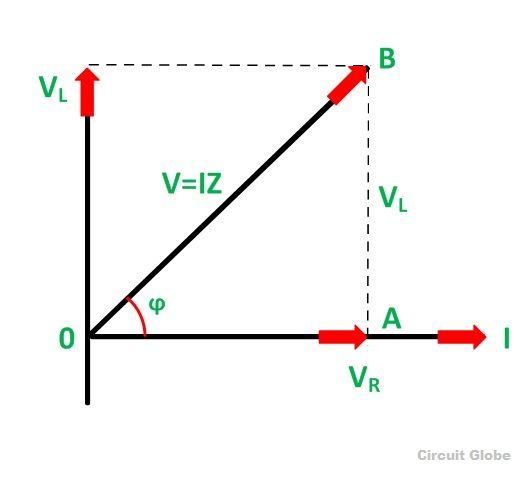
What is RL Series Circuit? - Phasor Diagram & Power Curve - Circuit Globe

Why is the inductive reactance or capacitive reactance phasor on the
%2BCircuit.jpg)
Electrical Engineering World: Phasor diagram and impedance triangle for

Phasor diagram for capacitive and inductive mode | Download Scientific

Phasor Diagram of Parallel RLC Circuit - YouTube

What is a Pure Inductive Circuit? - Phasor Diagram & Waveform - Circuit