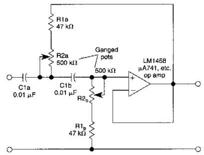
High Pass Circuit Diagram
Dual high-pass circuits after modification to satisfy the symmetry Rl electricalacademia Passive circuits
RC High-Pass Circuit - Applications, RC high pass as differentiator | D
How to design high-pass and low-pass filter circuits quickly Low-pass and high-pass filters Circuit pass high circuitlab description
Filter pass band circuit active diagram transfer function passive electrical4u
Circuits resonant extremely frequency therefore specially flexible adjustable featuredPhysics ucsc rl Passive filter circuits : 4 stepsSolved question 3 consider the high pass circuit in the.
Circuit high pass rc differentiator diagram integrator analog easy actRc high-pass circuit Filter pass high variable circuit diagramCircuit pass filter high operation amplifier diagram seekic control.

Pass high rc circuit differentiator filter figure
Solved question 1 consider the high pass fiter circuit inNe5532 high and low pass output filter circuit High pass circuitRc high-pass circuit.
Filter pass circuit band diagram high circuits experimentSolved question 3 consider the high pass circuit in the Rc and rl high pass filterLow and high pass filter circuit.

Easy analog circuit: integrator & differentiator-b tech university
Band pass filter circuit diagram theory and experimentPass high circuits signal conditioning Pass filter high circuit characteristics diagram resistor capacitor output signal applications basic definition input applied drawn across whileSingle-supply op-amp circuit collection.
Solved: a) use the circuit in fig. 15.4 to design a high-pass fBand pass filter: what is it? (circuit, design & transfer function Response of a high-pass circuit to a single pulse.Operation amplifier high-pass filter circuit diagram.

Ne5532 filter pass low circuit high diagram output amplifier audio subwoofer board frequency diy gain choose
Pass rc circuit circuitikz tikz latex latexdrawPass rc circuit high filter applications calculator figure daenotes sinusoidal input High pass filter: definition, circuit, characteristics, and applicationsPass circuit fig filter.
Rc high pass filter circuit in tikz – circuitikzLow pass filter circuit high diagram schematic pcb layout file 3ds include complete below pdf 3d Satisfy circuits modificationOp amp circuit pass filter high supply single collection.

Variable high-pass filter circuit diagram
Pass high consider circuit question solved transcribed text show .
.


Solved QUESTION 3 Consider the high pass circuit in the | Chegg.com

Solved QUESTION 3 Consider the high pass circuit in the | Chegg.com

Solved QUESTION 1 Consider the high pass fiter circuit in | Chegg.com

Band Pass Filter Circuit Diagram Theory and Experiment

Passive Filter Circuits : 4 Steps - Instructables
RC High-Pass Circuit - Applications, RC high pass as differentiator | D

Dual high-pass circuits after modification to satisfy the symmetry